Analog Temperature Indicator Circuit
This project was course work for EE230 at Iowa State, which I completed in Spring of 2026. The goal was to design a circuit around the LM35, a temperature-sensitive IC. Given a 5V input, the LM35 will produce a 0V output at 0°C, increasing by 0.01V for each °C, up to 1.5V at 150°C. The circuit must have three LEDs (green, yellow, red), which illuminate in sequence as the temperature changes. Implementation is an exercise for the student.
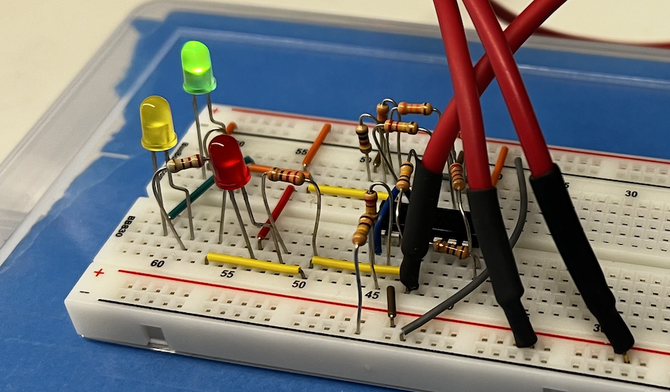 The physical circuit, on its breadboard.
Appears in these diary comics:
Specification
When temperatures are rising from 0°C, a Green LED is illuminated until 40°C, at which point the Green LED turns off and the Orange LED turns on. When temperatures reach 100°C, the Red LED turns on.
When temperatures are falling from 100°C, the Red LED extinguishes at 80°C. At 30°C, the Orange LED turns off and the Green LED turns on.
Design Process
The obvious solution is to use comparators with some hysteresis. Because comparators output binary signals, some clever wire routing can easily toggle between two LEDs with one comparator. The comparator's output changes which LED gets a voltage differential across its terminals. Only two comparators will be required, then: one to control the Green/Orange LEDs, and one to control the Red LED.

My lab kit has an LMC660C quad op-amp, which can be used to create the comparators and boost the LM35's signal. The LM35 demands 5V, so I plan to run the entire circuit off 5V.
First, the maximum useful signal we'll be getting from the LM35 is around 1V, so I grabbed some resistors that would give me a non-inverting opamp gain of <5. The first ones I found 100kΩ and 220kΩ, for a gain of 3.2.

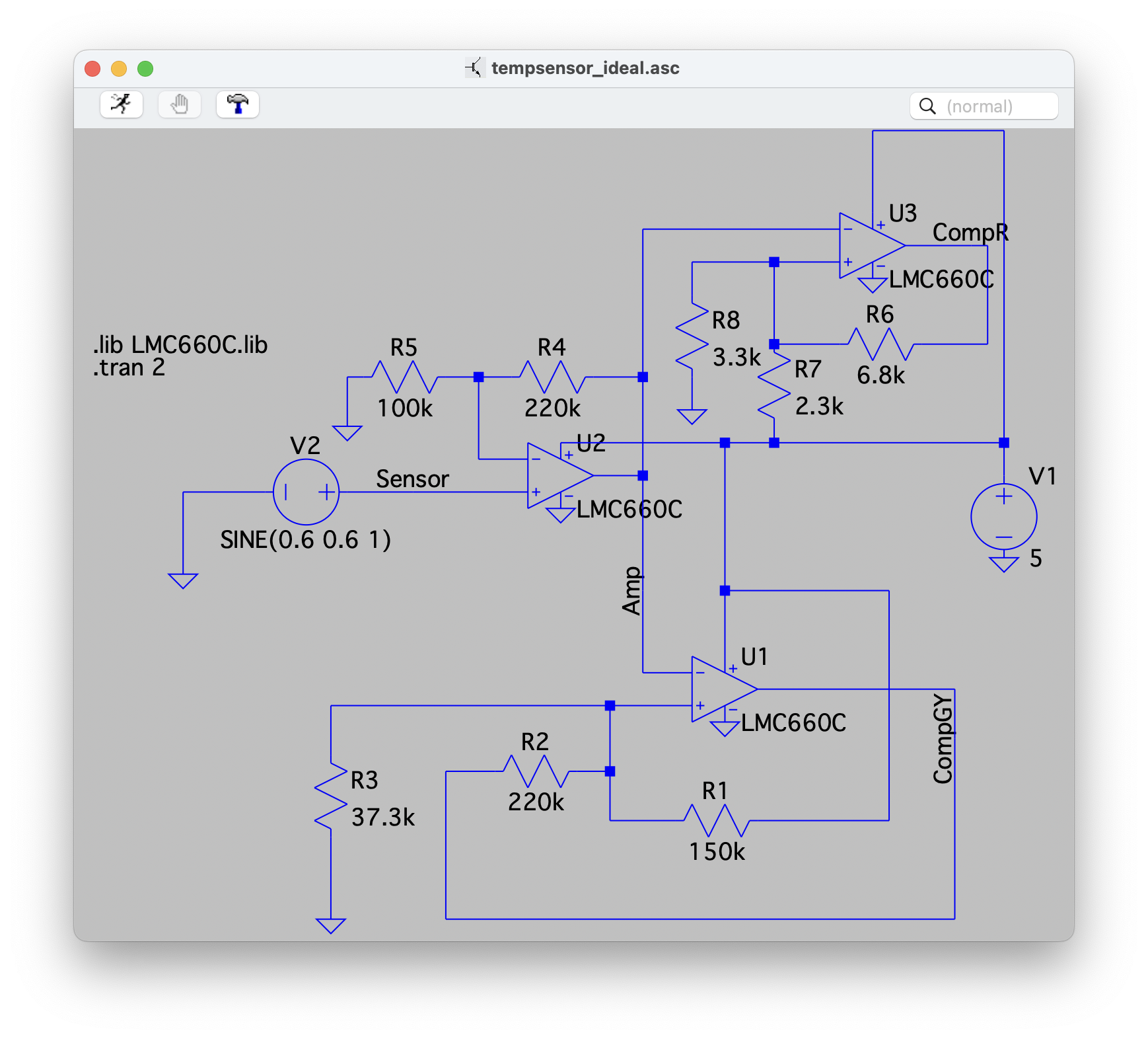
The comparators are more complicated. There are three unknowns in each comparator equation (the resistor values). I'm not very good at math, so I assumed two of the values, calculated the necessary third, and used that as a starting point to build the circuit in simulation.
Once I had the simulation, I adjusted each resistor individually and built a table of how changing those values affected the circuit. (We, uh, never talked about comparators in lecture.) In this way, I was able to determine that Rf seemed to have more of an affect on the width of the hysteresis, while the ratio between Rs and Rg determined the transition points.
The table of simulator values was helpful and accurate for determining how each resistor affects the circuit in reality, but it was not accurate for finding actual values in reality. So, the physical circuit required some trial-and-error, based on the adjustment behavior observed in simulation.
With this technique, I honed in on values of Rs = 150kΩ and Rf = 220kΩ for the Green comparator, and Rs = 2.2kΩ and Rf = 6.8kΩ for the Red comparator. Rg was then found via potentiometer for both comparators.
Schematic
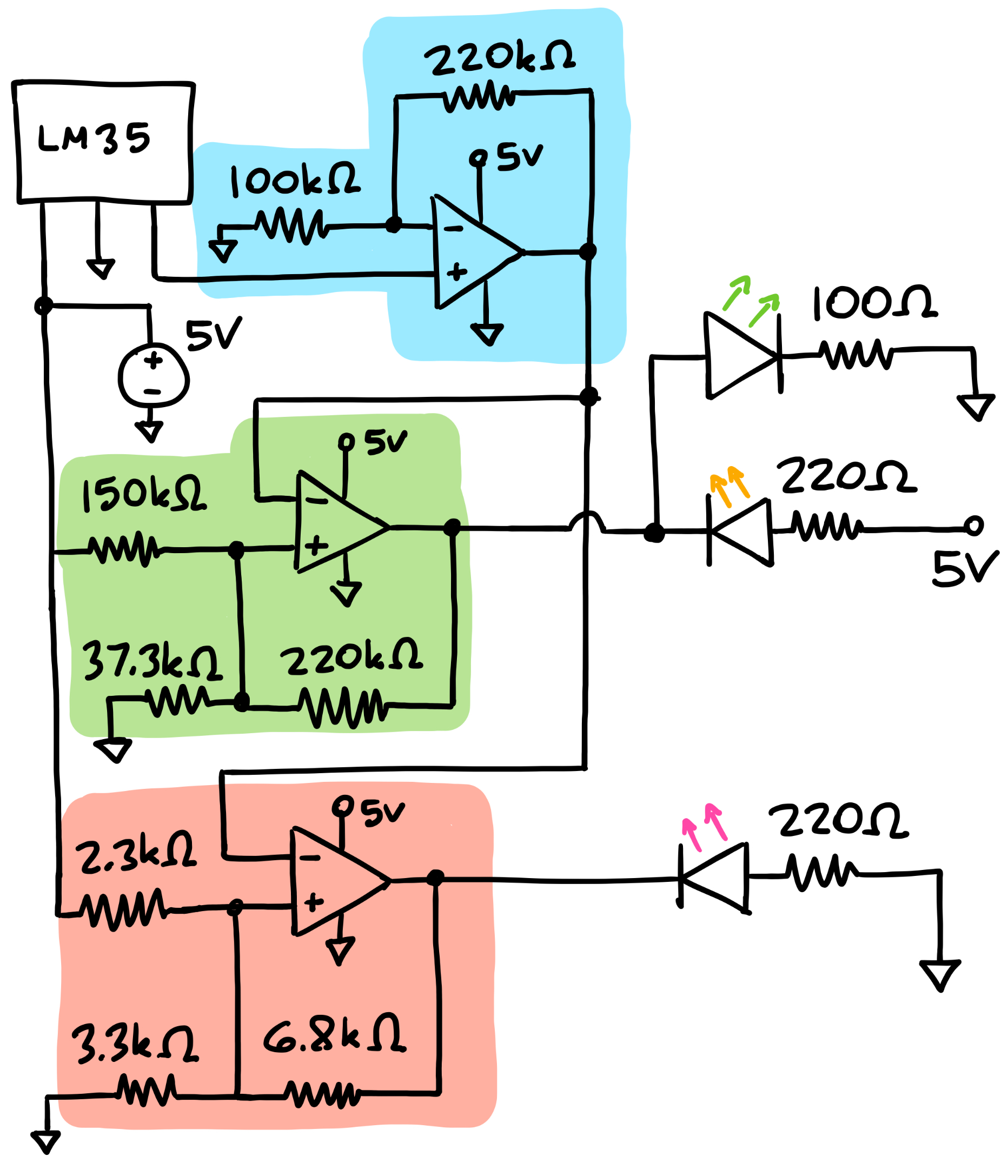
Blue Zone: Input Amplifier
Green Zone: Green/Orange LED Comparator
Red Zone: Red LED Comparator
Simulation
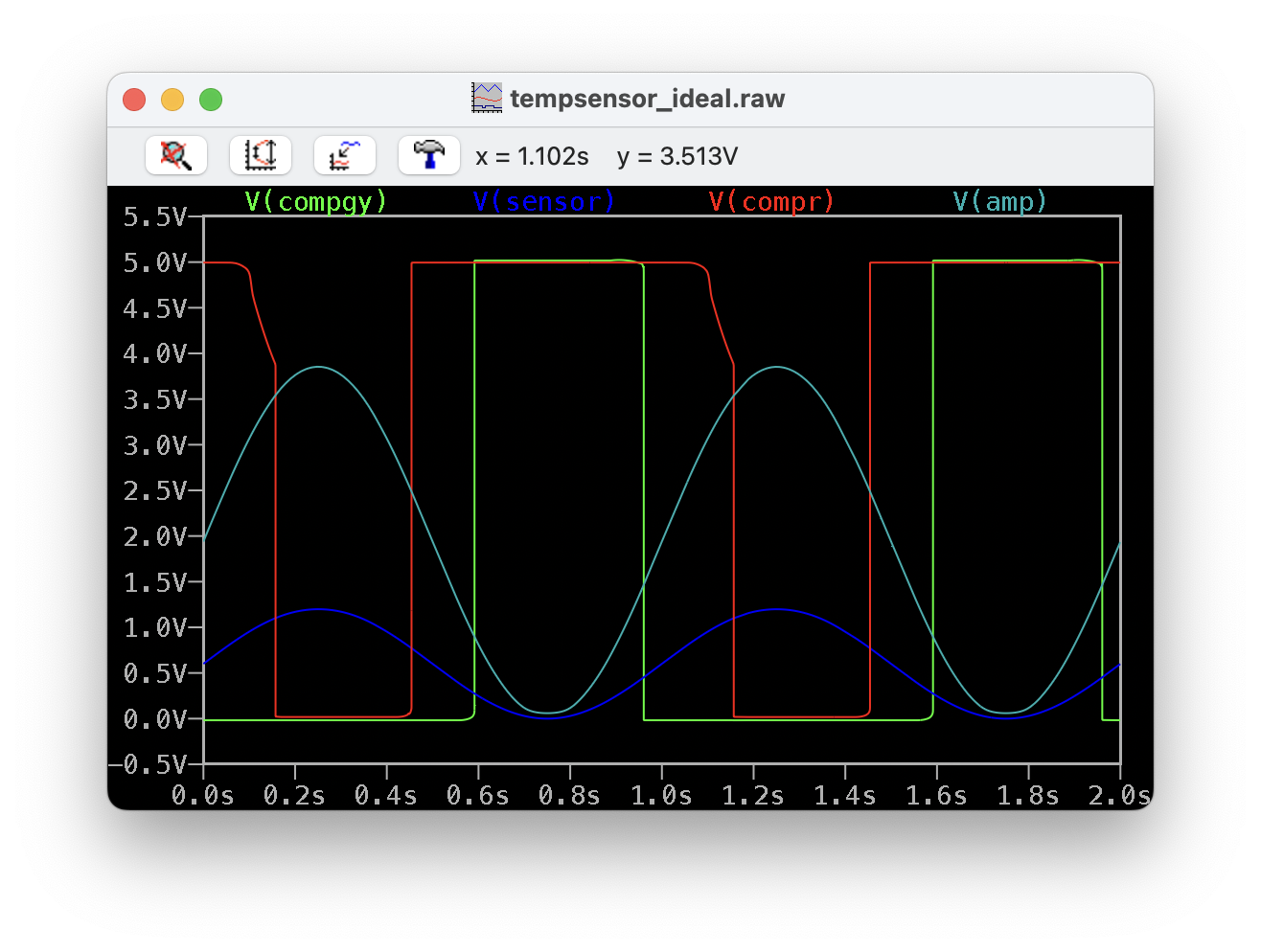
Dark Blue: LM35 Input Signal
Light Blue: Amplified LM35 Signal
Green: Comparator Output for Green/Orange LED
Red: Comparator Output for Red LED
Results
Rising Temperatures:
| LED State | Desired Value | Measured Value |
|---|---|---|
| 0 V | 0 V | |
| 0.4000 V | 0.4056 V | |
| 1.000 V | 1.025 V |
Falling Temperatures:
| LED State | Desired Value | Measured Value |
|---|---|---|
| 1.000 V | 1.000 V | |
| 0.800 V | 0.8112 V | |
| 0.300 V | 0.3001 V |
Actual Resistor Values
Amplifier:
- Rg: 100kΩ — 99.35kΩ
- Rf: 220kΩ — 220.0kΩ
Green Comparator:
- Rs: 150kΩ — 149.89kΩ
- Rf: 220kΩ — 220.69kΩ
- Rg: 37.3kΩ — 37.303kΩ (33.044kΩ + 3.2761kΩ + 0.9819kΩ in series)
Red Comparator:
- Rs: 2.2kΩ — 2.2492kΩ (2.1501kΩ + 0.9916kΩ in series)
- Rf: 6.8kΩ — 6.7365kΩ
- Rg: 3.3kΩ — 3.2822kΩ